Technical Guide: On-site Inspection, Installation & Acceptance of Diesel Generator Sets
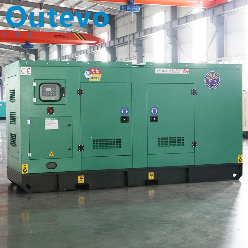
This article systematically introduces instrument accuracy requirements, load configuration schemes, and key electrical parameters for factory and on-site testing of diesel generator sets. It details pre-start equipment inspection checkpoints, operational parameter monitoring standards, and installation acceptance specifications. This guide provides comprehensive technical references for on-site commissioning, acceptance, and safe operation of generator sets.
1. Test Conditions & Pre-operation Equipment Inspection
Instruments with accuracy class 1.0 can be used for factory and on-site measurements of diesel generator sets. General tests shall be performed on fully pre-warmed generator units. Equipment power can be corrected according to ambient conditions as required by standards. For load testing, resistive loads or inductive loads with power factor ≥0.8 are recommended. Load steps shall follow: no-load, 25%, 50%, 75%, and 100% of rated power. For capacitive load tests, configure resistive loads equal to 100% of the unit’s maximum active output power, together with corresponding capacitive loads to achieve a leading power factor of 0.95. Unless otherwise specified, all electrical readings shall be measured at the output terminals of the generator control panel.
1.1 Pre-start Inspection for Diesel Engine
Before starting the generator, complete a full inspection of all diesel engine systems to eliminate hidden risks. (1) General fastening check: Confirm the unit is thoroughly cleaned. Check foundation bolts, flywheel fasteners and nuts on all moving parts for looseness and retighten if required. (2) Clearance & compression inspection: Verify all mechanical clearances, especially intake/exhaust valve clearance and decompression mechanism clearance. Set all cylinders to decompression position, crank the engine to listen for abnormal mechanical noise and confirm smooth rotation; crank the engine to feed lubricating oil to friction surfaces. Disable the decompression mechanism and crank again to check cylinder compression. High resistance while cranking indicates good compression performance. (3) Fuel supply system inspection: Ensure the vent hole on the fuel tank cap is unobstructed and clean any debris. Fill with diesel fuel of the correct grade and confirm sufficient fuel volume, open the fuel shut-off valve. Crank the engine under decompression; a crisp injection sound from each cylinder means proper fuel injection. If no injection sound or no fuel delivery is detected, air may be trapped in the fuel circuit. Bleed air by loosening vent screws on fuel filters and fuel injection pumps. Inspect fuel pipes and joints for leakage. Fill the injection pump and governor with lubricating oil to the specified oil level. (4) Cooling system inspection: Check coolant level in the radiator and top up with clean soft water when needed. Inspect pipe connections for leaks. Confirm the cooling pump impeller rotates freely and check the proper tension of drive belts. (5) Lubrication system inspection: Check oil pipes and fittings for oil leakage. Apply specified grease to all grease nipples. Pull out the dipstick to verify the oil level in the oil sump matches requirements; select oil grade according to local climate and season. If oil level is higher than the standard range, investigate three common causes: overfilling, diesel fuel leakage into crankshaft diluting oil, or coolant leaking into lubrication oil. (6) Electric starting system inspection: Check starter battery electrolyte density within 1.240~1.280 kg/L. A reading below 1.180 kg/L indicates low state of charge. Inspect wiring correctness; clean corrosion and dirt on battery terminals. Confirm good electrical contact for starter motor and electromagnetic actuator.
1.2 Installation Check for Alternator
(1) Coupling tolerance requirement: When coupling the alternator and diesel engine, the parallelism and concentricity of the coupling shall be less than 0.05 mm; for field application, it can be relaxed within 0.1 mm. Excessive misalignment damages bearing operation. Fix the coupling with locating pins after alignment, and recheck alignment before installation. (2) Alternator with sliding bearings: The center height of the alternator shall be slightly lower than the diesel engine, to prevent the flywheel weight from transferring to the alternator bearing. This avoids extra load that breaks the bearing oil film and leads to overheating or burnout. No extra heavy objects can be attached to the coupling. (3) Ventilation & protection: Ensure unobstructed cooling air inlet. Prevent hot exhaust air from recirculating back into the alternator. Louvers on ventilation covers shall face downward to meet IP protection requirements. (4) Single-bearing alternator: Special care is required to maintain uniform air gap between stator and rotor during mechanical coupling. (5) Electrical wiring: Select proper power cables and copper lugs according to wiring diagrams. After tightening copper lugs to busbars, local gaps at joints shall not exceed 0.05 mm. Keep conductor spacing greater than 10 mm and install required earthing conductors. Terminals inside the outlet box are marked U, V, W, N. The actual phase sequence depends on rotation direction rather than these fixed marks.
2. Technical Performance Indicators & Operational Monitoring
2.1 Voltage Stability Performance
When the generator set is loaded or load changes, output voltage will shift to a new value. The time taken for stabilization is voltage settling time, normally between 0.5 ~ 3 seconds. Shorter settling time represents faster response to load variation. Steady-state voltage regulation rate is calculated as the percentage difference between the stabilized voltage and no-load set voltage, typically ±3% ~ ±5%. It reflects the unit’s capability to regulate voltage under load fluctuations.
2.2 Frequency Stability Performance
Frequency stability describes how output frequency changes with load. Two key parameters are frequency settling time and steady-state frequency regulation rate. Lower values indicate better response and frequency control against load changes.
2.3 Fuel Economy Indicators
(1) Specific fuel consumption: Fuel mass consumed per kW effective power output per hour, unit: g/(kW·h). It is the core metric for diesel engine fuel efficiency. (2) Effective efficiency: Ratio of heat converted into useful mechanical energy vs total heat released from fuel consumption, measuring how efficiently chemical energy in fuel converts to mechanical work.
2.4 Key Monitoring Parameters During Operation
(1) Ammeter: Check current readings. Switch between phases to measure phase current; phase imbalance should not exceed 10%. (2) Voltmeter: Monitor output voltage continuously. (3) Charging system: Charging indicator should show positive (+). Negative (-) reading means the battery is not charging. (4) Oil pressure gauge: Maintain lubrication oil pressure within manufacturer specified range. (5) Coolant temperature gauge: Normal operating temperature range: 65~93°C. Stuck reading or temperature above 93°C is abnormal. (6) Tachometer: Monitor engine rotation speed. For 60Hz power system, rated speed is 1800 r/min. (7) Sound & vibration: Listen for abnormal noise and vibration during operation.
3. Installation Acceptance Specifications
3.1 Installation Location & Environmental Requirements
(1) The rated voltage of the on-site generator set must match the required system voltage. (2) Fixed diesel generator sets shall be mounted on engineered indoor foundations, elevated 0.25~0.30 m above the floor. Portable/trailer-mounted units must stay level and stable. Trailers require reliable earthing and wheel chocks. Outdoor units need protective shelters. (3) Generator sets, control cabinets and switchgear rooms shall reserve proper electrical safety clearance and meet fire protection requirements. Exhaust pipes must route outside the building. Fuel storage tanks shall never be placed indoors or near exhaust piping. (4) Locate the generator close to load center for convenient cable routing and site access. Avoid low-lying flood-prone areas and locations downwind of pollution sources.
3.2 Electrical Interlock & Parallel Operation
(1) Generator output must be electrically interlocked with utility grid supply. Parallel connection with public grid power is strictly prohibited. (2) When two or more generator units run in parallel, synchronizing equipment must be fitted. Load connection can only be made after successful synchronization.
3.3 Foundation, Installation & Earthing
(1) Foundation dimension, strength, vibration isolators, reserved openings, cable trenches and covers shall comply with design specifications. (2) The generator shall be firmly installed. Foundation anchor bolts use post-grouting installation, with consistent exposed thread length. Vibration dampers shall be fitted between the unit and base frame as per design. (3) Fuel pumps, tanks, water pumps and radiators shall be mounted level and secure. Fuel pipelines shall run straight without leakage. Fuel pipes are painted reddish-brown with red flow direction markers on branches. (4) Starter battery installation follows design layout; complete charge/discharge test records must be retained. (5) Power cables and signal cables shall be routed per drawing requirements. AC power cables, DC power cables and signal wires shall not be bundled together. (6) Generator unit, base frame and fuel tank all require reliable earthing connection.
3.4 Acceptance Test Criteria
(1) Before commissioning, test insulation resistance of generator and exciter windings (inter-winding and winding to earth) using a 500V megger. Insulation resistance shall be greater than 2 MΩ. (2) No-load test: The engine runs smoothly with accurate governor control and stable speed. No abnormal noise or overheating. Voltage, current, frequency and temperature, pressure gauges read normally. (3) Load test: Automatic voltage regulator and governor perform well. Oil temperature, water temperature and oil pressure stay within normal range. No abnormal noise. Fuel, lubrication and cooling systems operate properly. No exhaust leakage; light blue exhaust smoke is normal. (4) After the monitoring system is activated, functions including automatic start, automatic stop, voltage & frequency adjustment, fault alarm and fuel level indication shall work as designed.
Summary
On-site inspection and installation acceptance of diesel generator sets covers instrument accuracy control, staged load testing, pre-start checklists, runtime monitoring and installation acceptance. Adhering to Class 1.0 measuring instruments, multi-stage load testing, six-system pre-start inspection and seven core runtime monitoring metrics ensures reliable unit performance. Solid foundation installation, proper earthing, interlock protection and commissioning tests are all essential. Full compliance with standardized procedures guarantees safe, stable and efficient operation for both standby and prime power applications.
Media Contact
Shanghai Outevo Machinery Co.,Ltd.
Web: www.outevo.com
Tel: +8613280091753
Anne
